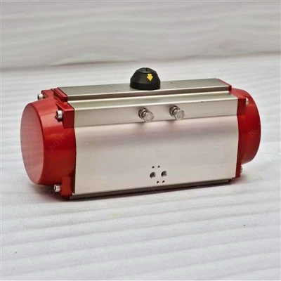
As a supplier of hydraulic linear actuators, I’ve encountered numerous inquiries regarding the control of actuator speed. This topic is crucial as the speed of a hydraulic linear actuator significantly impacts its performance and the efficiency of the entire system it operates within. In this blog, I’ll share insights into the various methods to control the speed of a hydraulic linear actuator. Hydraulic Linear Actuator
Understanding Hydraulic Linear Actuators
Let’s first understand the basic working principle of hydraulic linear actuators. These actuators are devices that convert hydraulic energy into linear mechanical motion. They consist mainly of a cylinder body, a piston, and a rod. When pressurized hydraulic fluid is introduced into one side of the piston, it creates a force that moves the piston and the attached rod either in an extending or retracting motion.
The speed of a hydraulic linear actuator is determined by two main factors: the flow rate of the hydraulic fluid and the cross – sectional area of the piston. The relationship can be described by the following formula:
[v=\frac{Q}{A}]
Where (v) is the speed of the actuator, (Q) is the flow rate of the hydraulic fluid, and (A) is the effective cross – sectional area of the piston. So, to control the speed of the actuator, we can either adjust the flow rate of the hydraulic fluid or change the effective cross – sectional area of the piston.
Controlling Speed by Adjusting Hydraulic Fluid Flow Rate
Throttle Valves
One of the most common methods to control the speed of a hydraulic linear actuator is by using throttle valves. Throttle valves are designed to restrict the flow of hydraulic fluid in the system. By adjusting the opening of the throttle valve, the amount of fluid flowing to the actuator can be regulated.
There are two main types of throttle valves: fixed – orifice throttle valves and variable – orifice throttle valves. Fixed – orifice throttle valves have a constant opening size, which limits the flow rate to a pre – determined value. These are typically used in applications where a fixed speed is required.
Variable – orifice throttle valves, on the other hand, allow for the adjustment of the flow rate during operation. They provide greater flexibility as the speed of the actuator can be changed according to the specific requirements of the task. For example, in a manufacturing process where different stages require different actuator speeds, a variable – orifice throttle valve can be adjusted accordingly.
Flow Control Valves
Flow control valves are another effective way to regulate the flow rate of hydraulic fluid. Unlike throttle valves that simply restrict the flow, flow control valves are designed to maintain a constant flow rate regardless of the pressure variations in the system.
There are two main categories of flow control valves: non – compensating and compensating flow control valves. Non – compensating flow control valves are relatively simple and less expensive. However, their flow rate is affected by pressure changes in the system. Compensating flow control valves, on the other hand, use pressure – compensating mechanisms to ensure a constant flow rate even when the pressure in the system fluctuates. These are ideal for applications where accurate speed control is necessary.
Pump Control
The speed of a hydraulic linear actuator can also be controlled by adjusting the output flow rate of the hydraulic pump. Variable – displacement pumps are commonly used for this purpose. These pumps can change their displacement volume, which in turn changes the flow rate of the hydraulic fluid they deliver.
By regulating the displacement of the pump, the flow rate of the fluid supplied to the actuator can be adjusted, thereby controlling the speed of the actuator. This method is particularly useful in systems where large – scale speed adjustments are required. For example, in heavy – duty construction equipment, a variable – displacement pump can be used to adjust the speed of the hydraulic linear actuators according to the different working conditions.
Changing the Effective Cross – Sectional Area of the Piston
Differential Cylinders
Differential cylinders are a type of hydraulic linear actuator that can change the effective cross – sectional area of the piston. These cylinders have different piston areas on the rod side and the base side. When the hydraulic fluid is introduced into different sides of the piston, the resulting force and the speed of the actuator can vary.
During the extension stroke, the hydraulic fluid is usually supplied to the base side of the piston. The effective cross – sectional area is relatively large, which results in a slower but more powerful movement. During the retraction stroke, the fluid is introduced to the rod side, where the effective cross – sectional area is smaller, and the actuator moves faster. Differential cylinders are commonly used in applications where different speeds are required for extension and retraction, such as in some types of lifting equipment.
Multi – Stage Cylinders
Multi – stage cylinders are another option for changing the effective cross – sectional area of the piston. These cylinders consist of multiple nested stages. As the cylinder extends, each stage is activated in sequence, and the effective cross – sectional area changes accordingly.
In the initial stage, the cross – sectional area is relatively large, providing a slow but high – force movement. As more stages are extended, the cross – sectional area decreases, and the speed of the actuator increases. Multi – stage cylinders are often used in applications where a long stroke is required along with variable speed control, such as in dump trucks.
Considerations for Speed Control
When controlling the speed of a hydraulic linear actuator, several factors need to be considered. Firstly, the load on the actuator has a significant impact on its speed. A heavier load will generally require more force to move, which may affect the speed even if the flow rate or cross – sectional area is adjusted.
Secondly, the viscosity of the hydraulic fluid can also influence the speed control. The viscosity of the fluid changes with temperature. In colder temperatures, the fluid becomes more viscous, which can reduce the flow rate and slow down the actuator. Therefore, it’s important to choose the appropriate hydraulic fluid and maintain a suitable operating temperature.
Thirdly, the efficiency of the hydraulic system, including the valves and the pump, can affect the speed control. Leakage in the system can lead to a loss of fluid pressure and flow rate, resulting in inaccurate speed control. Regular maintenance and inspection of the hydraulic system are essential to ensure its proper functioning.
Conclusion
Controlling the speed of a hydraulic linear actuator is a complex but crucial task. By adjusting the flow rate of the hydraulic fluid through methods such as throttle valves, flow control valves, and pump control, or by changing the effective cross – sectional area of the piston using differential cylinders or multi – stage cylinders, the speed of the actuator can be effectively regulated.
When it comes to choosing the right speed – control method, it’s important to consider the specific requirements of the application, such as the load, the operating temperature, and the required accuracy of speed control. As a trusted supplier of hydraulic linear actuators, we have a wide range of products and solutions to meet your needs. Whether you need a standard actuator with basic speed – control features or a customized solution for a complex application, we can provide you with professional advice and high – quality products.
Rack And Pinion Actuator If you’re interested in our hydraulic linear actuators or have any questions about speed control, please feel free to contact us. We’re looking forward to starting a productive discussion with you and helping you find the best solution for your project.
References
- Fluid Power Handbook, Ninth Edition, by International Fluid Power Society
- Hydraulic and Pneumatic Systems: Design and Application, by George Ellis
- Industrial Hydraulics Manual, by Parker Hannifin Corporation
Zhejiang Bigtork Valve Automation Co., Ltd.
Zhejiang Bigtork Valve Automation Co., Ltd. is one of the leading hydraulic linear actuator manufacturers and suppliers in China. We warmly welcome you to buy customized hydraulic linear actuator at competitive price from our factory. Contact us for more details.
Address: 98 Yuanqu Avenue,Anfeng Industrial Zone,Oubei,Yongjia,Zhejiang,China.
E-mail: sales@bigtork.com
WebSite: https://www.bigtork.com/
